FT-817 basics: making the receiver sound good

The importance of properly adjusting the RF gain on the FT-817 has been pointed out numerous times, but I think it bears repeating – especially for newcomers to amateur radio who might have purchased a Yaesu FT-817 or think about doing so. My opinion: go for it! This rig will provide you with fun for years to come, regardless of other gear you might acquire in the future.

Many say the FT-817’s receiver is bad. Well, yeah, it might not be the best. Especially on CW on the lower bands, without extra filters, you might hear many signals at the same time, which can be a bit distracting but also instructive: it’s good for practicing ‘hearing’ and concentrating on a single signal; after all, our mind is more powerful than any technical gizmo. We don’t need to rely on technology in everything we do!

But back to adjusting the RF gain. On the FT-817’s receiver, you have basically 3 major things you can tweak:

  • RF-gain. It’s the knob behind the volume control. Attention: in some cases, it might be configured to act as squelch, in which case you need to enter menu Nr. 45 and change the functionality of the knob.
  • IPO. You find the IPO (Intercept Point Optimization) on the A button. It bypasses the RX preamplifier and really helps to bring out the best in the FT-817’s receiver. Press the F key to adjust the function of the A-B-C buttons so that “IPO” shows up.
  • ATT. The attenuation function is on the B button and further reduces the RF gain.

Especially on 80 and 40 meters, what you want to do is activate the IPO function and reduce the RF gain on the RF gain knob to near zero, then turn it up again slowly. If you don’t hear anything, wait a little until the AGC circuit (automatic gain control) catches up.

Whether you are trying to understand a weak signal or hear a very loud one, these simple steps really help. When listening to a loud station, they prevent the AGC from bringing up all the noise and nearby stations when the station goes silent or pauses; when listening to a weak station, they prevent the AGC from reducing the volume even further when nearby stations boom in. These settings seem to improve selectivity in general as well.

Here’s a little video I made demonstrating the effects of RF gain and IPO:

Try it for yourself and see what it can do for you.

73’s and good luck!

Book review by KB6NU and some musings on obsession

Dan, KB6NU, wrote a very kind review of my book “Ham Radio Boost“. Thank you, Dan!

I think he really grasped what it is all about – the human side of ham radio and the various ways in which we hams can make our lives more difficult than it should be.

He does make one interesting point about the contradiction between ‘avoiding obsession’ and ‘being committed’:

Some of the advice may seem contradictory. For example, lesson #1 is to avoid being obsessed with amateur radio, yet one of the chapters is titled, “Commitment is king.” Life is like that, though, isn’t it? The trick is being able to resolve those conflicting ideas in our lives. In this case that means not being obsessed with the hobby while at the same time being committed to it. Without commitment you won’t get as much out of amateur radio as you might expect, but you still do need to be able to step away when you need to as well.

Indeed, life is like that methinks – it can be contradictory, there can be pulls in opposing directions, and there can be conflicting rules in our ethics and outlook on life.

Here is how I personally go about the conflict between commitment and avoiding obsession: I think obsession is like a tunnel we can enter that makes us forget everything and everyone, even people and things that are very dear to us. In such a state, our focus can become extremely narrow. Now, this can sometimes be a good thing: sometimes we just need a lot of concentration and focus to achieve something worthwhile. However, if the balance is lost and the whole thing becomes totally unreasonable, then I call it obsession.

For example, if I work for hours on a project, running in circles and becoming irritated when I get disturbed – even without really advancing my project anyway -, then this is not good. Oftentimes, I found it much more productive to work on a ham radio-related project for 2 hours or so and then do something else. I can still come back the next day or whenever I find some time, and oftentimes I come back to the project with fresh ideas and solutions. My unconsciousness probably figured it out while my mind was occupied with other things – an interesting phenomenon that we can use to our advantage.

Or think about it this way: how does such obsession, i.e. spending 8 hours straight on a project, affect others in your life? I don’t think, for example, that letting my wife clean the house alone even though I could help her just so that I can fumble with my ridiculous ham radio project is very nice. Maybe there are repairs in the house to make. Maybe I could do something I have promised a friend. And so on. When ham radio obsession interferes with other duties and commitments, it’s really not helpful and doesn’t make ham radio look too good in the eyes of others either.

Which brings me to commitment. For me, commitment to ham radio means doing things I’m not necessarily crazy about at the moment, but which I know are important and make me happy in the long run. This includes practicing patience, being a reliable club member who does what he promises, or practicing my radio skills on a continuous basis – not in radio binge sessions, but consistently.

In other words, commitment is when you practice CW for 30min even though you want to surf on the internet. When you go to the club meeting even though you feel tired and want to watch TV. When you write that QSL card even though you want to watch a movie. That sort of thing. Commitment is difficult and rewarding in the long term, whereas obsession is easy and potentially harmful.

At least that’s my take on it. Feel free to share what you think!

Troubleshooting the TNC Pi

About 3-4 years ago, I purchased the TNC Pi, a little board for the Raspberry Pi that functions as a TNC. Its main purpose is to let you operate APRS on a Pi – it’s also easy to build an APRS digipeater around it.

dscf2646

TNC Pi troubleshooting – for years!

Back then, I couldn’t get it to work at all. I fiddled around with the software for hours, checked the connections on the board – nothing. The LED would blink, but no luck connecting to the board from the Pi.

So the Pi with the board sat there in its little corner, accusing me of my incompetence. Now, after all these years, it irked me so much that I finally decided to attack the thing once more. I booted the original Pi 1, googled around, tried every software combination, tried to activate the I2C bus etc. etc. – no luck.

Okay, it must be the hardware then. I checked all kinds of continuity issues. Found nothing. I changed the red LED, which I found out wasn’t working, but that’s only cosmetics, it’s not really needed. No luck still.

And then things got interesting. I often found that once I’m done with trial and error and looking for the quick fix, the real learning experience starts. I knew I had to delve into the schematic of the little board, and so I did. Of course, I don’t understand exactly how the thing works, but with a design that is essentially IC-driven, ‘understanding’ is more a matter of checking that all connections go to the right places.

dscf2648

Delving into the schematic of the TNC Pi finally brought the answer

Since the voltage test recommended in the manual was positive, the LED’s were blinking and the modem was decoding when I sent the board an APRS packet (as indicated by the yellow LED), I knew that the problem was that the Raspberry couldn’t talk to the PIC chip on the TNC Pi.So I focussed my search here.

Sure enough, after lots of continuity testing and patching this or that, it became obvious that at least 2 connections from the Pi to the PIC chip were broken. Crucial connections needed for communication! No wonder I couldn’t talk to the board. The reason? A very, very sloppy soldering job 3-4 years ago. I’m ashamed. But then again, that was one of my very first projects ever.

Back then, I used a ridiculously inadequate solder – an extremely thick one, which only melts above 400°C! I guess they produce it for heavy-duty soldering jobs, but certainly not for any work in electronics. I also had a totally inadequate soldering iron back then, which didn’t help either.

Just for good measure I let the solder flow again to most joints, and sure enough – it worked! Another confession I have to make here is that until now, I had no clue that on such pre-fabricated boards, the solder has to actually flow into the hole – it’s not enough that there’s continuity between the component and the soldering joint! Of course, the joints must be connected to the conductor on the board! Duh.

So it came down to my inexperience in the art of soldering and my lack of understanding of the basic principles of manufactured electronic boards. All the software fiddling was for nothing – or not exactly, I learned quite a bit about how packet radio and APRS work, especially on Linux.

And that’s the beauty of our hobby – we learn stuff. Especially if it doesn’t run plug-and-play and we need to delve into it in order to make it work. So even though I had been frustrated for almost 4 years with this projects, now I can say I’m thankful, and it was totally worth it!

(Now I just need to do something with the TNC Pi setup – I think I will set up an experimental APRS digipeater, since the big one near my location seems to have gone silent.)

Simple End Fed Half Wave for 40m (and how it works)

I’ve heard very good things about end fed half wave antennas, so I wanted to give it a shot. The problem is that it’s not so easy to understand, and I found most designs I looked at on the web a bit confusing. Also, they are mostly multiband designs, which doesn’t help either. That’s why I thought I’d start simple and build a monoband version of this antenna.

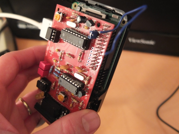
This is my attempt at explaining what I understood and a step by step instruction on how to build a monoband end fed half wave antenna coupler. So this thing is the result:

dscf2634

Understanding the end fed half wave

I highly recommend AA5TB’s page about this antenna, which explains the concept in more detail. First, it is important to understand the difference between the end fed half wave and a random wire (or “long wire”) antenna: the random wire is just a piece of wire that is matched to 50 Ohm impedance using an antenna coupler, sometimes adding a 9:1 unun. The end fed half wave, on the other hand, is exactly a half wavelength long on the desired frequency – think of it as a regular dipole, only that it is fed at the end and not in the middle. The current/voltage distribution of the dipole looks like this:

0613wtdantennas_fig2

As you can see, if we feed this antenna on one of the ends instead of the middle, there is near zero current flowing, but we are faced with very high voltages. In other words, the impedance at the end of the wire is extremely high – a couple of thousands Ohm. This is the reason why we need a transformer that transforms the very high impedance at the end of the “dipole” down to the 50 Ohm impedance of our transceiver. We do this by using a coil with a primary winding at the transceiver side and a secondary winding at the antenna side. The ratio of the turns squared is the ratio of the transformation.

Following one of AA5TB’s suggestions, I went with 3 turns primary and 28 turns secondary. This equals a ratio of 1 to 9,3, which equals a transformation of 1:9,3² = 1:87. This should transform an impedance of 4350 Ohm down to 50 Ohm.

Advantages of the end fed half wave

Since it acts like a dipole, this antenna has the advantage of being more predictable and reliable than a random piece of wire. Also, there shouldn’t be any RFI or “RF in the shack” problems, because the current at the feed point is extremely low. Since there is no power wasted zapping you, this antenna should be very effective. Most importantly, you don’t need any counterpoise for this antenna, or at least only a very small one (0.05 Lambda, more on this later).

Another advantage of the EFHW is that unlike most QRP antenna couplers, there are no variable capacitors used that typically can’t handle much power. So if you use a good, high-voltage rated capacitor, your only limiting factor is the toroid cors. The Amidon FT-240-43 core is known to handle 100W easily on SSB, and while it’s not small, you can still fit it into a very quite small enclosure.

Note that on CW and digital modes, you really need to be careful – the core can get warm if you pump too much power into it and this may screw your SWR!

Compared to the dipole, the end fed half wave is more practical: we can feed it at the bottom of a mast or tree, or even just throw the wire out of the (attic) window. No need for heavy feedlines or multiple supports. Also, since we don’t need a lot of feedline (or none at all), feedline losses are minimized.

All in all, it is a very versatile antenna and lends itself perfectly for emmergency communication where you want to be able to deploy the antenna very fast. Just like the dipole, it can be used in an NVIS configuration.

To ground or not to ground?

This question can be a bit confusing. Some designs connect one end of the secondary coil to the antenna socket, which then makes the coax shield act like a counterpoise. Other designs, such as the popular commercial EFHW-8010, connect it to s separate screw/output so that you can either connect a short counterpoise or connect it to a ground rod.

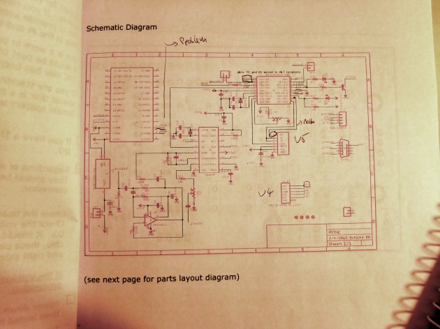
I opted for the latter option because this makes the design independent of the length of coax used. Because of the low current at the feed point, you only need a very small counterpoise anyway – AA5TB recommends 1m. Also, this way the coax is not connected electrically (in a DC sense) to the antenna, which I hope helps with keeping static discharges away, especially when operating portable and the station is not grounded. Here is the schematic:

Schematic of a simple end fed half wave coupler

Schematic of a simple end fed half wave coupler

As I said earlier, I used 3 turns for the primary and 28 turns for the secondary. As for the ground rod, my understanding is that it helps with safety (static etc.), so it might be a good idea to use one. I’m not sure whether it makes any difference in terms of RF.

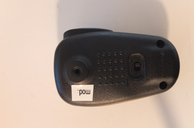
Construction of the EFHW coupler, step-by-step

What you need:

  • A toroid or ferrite core (should be large enough)
  • Enameled wire (I used 0.5mm wire, but this is not very critical)
  • A suitable case (I used an electrical case from the DIY store – fits perfectly)
  • Some kind of socket or screw-type terminal for the antenna wire and counterpoise
  • A drilling machine (though with the case I used, a knife will do)

A word about the toroid/ferrite: it is my understanding that most will do, so you can just try what you have available. However, I read somewhere that for the lower bands (40m and down), the core should provide a high enough inductance to work properly. I’m not sure I really understand why, but there it is. I used a TN 23/14/7 4C65 ferrite core, which has an AL value of 87 nH. With my 28 turns on the secondary, I measured 0,07 mH. I think (hope) that should be plenty enough.

Next, look at the box you want to build it into and figure out where the toroid and connectors should fit. It helps to draw it on a piece of paper.

Wind the toroid. You need one shorter piece of wire for the primary and one longer piece for the secondary. Twist the shorter piece with the larger piece and wind 3 turns tightly with this twisted wire (one turn means the wire passing through the inside of the toroid one time). If you don’t have a multimeter, you should mark the short wire (maybe with a piece of tape) on both ends so that you know which end is which.

After the three turns, let the shorter wire dangle away and keep winding the longer wire 25 more times.

dscf2635

Mount your connectors and figure out how to route the wires to them.

Now you need to get rid of the lacquer at the end of the wires – I do this by carefully applying very hot solder to the ends of the wire and gently “pushing” the lacquer away with the hot solder.

Now comes the important step of checking if the transformation works as intended. For this, you need to put a resistance of about 4k Ohm across the antenna and ground wire. I used a couple of resistors in parallel to obtain that (unlike in the picture, I used 4 resistors, which gave about 4000 Ohm):

dscf2627

Now connect your transmitter (and SWR meter, if your transceiver doesn’t have one) or antenna analyzer and apply (low) RF power on the desired frequency, in this case 7.1 Mhz. You should get a very good match. If satisfied, solder the wires to all the connectors.

Now comes the time to connect the antenna wire/counterpoise. I haven’t completed this step myself, but it should go like this: Cut about 20m of wire (maybe a little more) and connect it to the antenna jacket/screw. Deploy it the way you actually intend to use it!

Now check SWR and if necessary, shorten the wire step by step until you get a good-enough match. You can fold the wire onto itself to make easy adjustments.

Voilà!

dscf2632

When I find some time to adjust and test this antenna in the field, I’ll post an update. If I got anything wrong here or you can explain some more of the theory behind the EFHW, please let me know! I’m still struggling to understand it myself.


UPDATE: I had the chance of trying this antenna while I was Denmark as OZ/DH7LM. It worked very well!

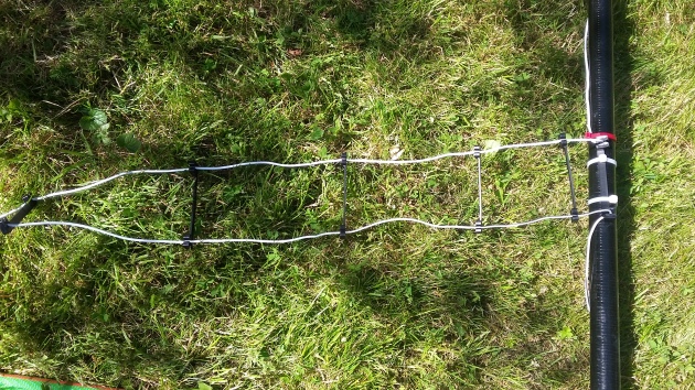
I had to cut the wire several times until the SWR was very low in the 40m band – I could use the entire band. Results were very good, comparable with a regular dipole. I ran the wire to a 12m Spiderbeam mast, inverted Vee style:

I also experimented with using a short radial of about 1m length, which interestingly increased the operating frequency a bit, while also increasing the SWR slightly. The bandwidth seemed a little narrower as well. That’s why I ended up not using the radial after all. I didn’t make any A-B tests though – maybe the slightly higher SWR and lower bandwidth is a sign that the antenna  is a bit more effective with the radial? Still experimenting…

But I’m glad that the transformer worked exactly as intended and I had good results on the bands. Yay!

End-fed half wave monoband antenna


Like back in the days: radio assistance on the road

I must admit that I sometimes regret not having been around as a ham when amateur radio really had practical advantages. In a world without mobiles and GPS, hams could still communicate with others while on the road and most importantly, they could help each other. They were far ahead of ordinary people, so to speak. Not anymore – today, everyone can access the internet from their smartphone, make calls using the car audio system or be warned by their GPS about traffic jams. Yes, sometimes I regret not knowing how it feels like to be the only one able to communicate on the road. But I know this is a selfish thought, born of the desire to ‘be special’ and superior, so I try to avoid such irrational thoughts.

Anyway, when my wife and I were driving to a family holiday this summer, I experienced the helpfulness and ham spirit that I so like about the hobby and that was always part of ham radio culture: I was assisted very kindly by two hams in finding my way out of a traffic jam, which was caused by an accident and led to a total interruption of the traffic. Nothing moved. You know it’s bad when people start going on walks on the highway! Even the commercial FM stations didn’t report it yet and nobody seemed to know what was going on and what to do.

baofeng2

Baofeng UV-5R mounted in the car for mobile operation

So I called on the 2m calling frequency 145,5 Mhz with my little Baofeng walkie-talkie hooked up to a Diamond MR-77 mag mount antenna. Normally, no one answers calls on the 2m direct frequency anymore – sadly, in this day and age, most amateurs don’t bother monitoring the frequency. But not this time: a local guy came back loud and clear, apparently they have a morning round each weekend on 145,5 (which kind of proves that this calling frequency is dead; otherwise, they couldn’t hold their rag chews there!). I told him about the traffic jam and he described in detail a possible ‘escape route’, involving taking the next exit, which he assured me was very close to my position. Since he’s a local, he knew exactly where I needed to go.

We took his advice and started the maneuver when another ham called in:”Stop, stop! The traffic jam will clear just in a couple of minutes! Stay there!” Sure enough, he was right – five minutes later we were back on the move. Had we taken the exit, we would have lost quite some time I guess. I thanked them both for the not only very pleasant but very helpful QSO and said my 73’s. What a lovely ham radio experience!

Just because there are mobiles, GPS and what have you, this doesn’t mean ham radio can’t be useful anymore. It’s the ham spirit, the helpfulness and kindness in the community that makes all the difference. Plus, since we had the QSO on a direct frequency, we all were quite independent of any network infrastructure whatsoever, we didn’t even have to rely on a local repeater. Cool!

A vertical dipole for the higher bands (ladder line-fed)

While I spent a little time in France, I wanted to operate “holiday-style” a bit to work a few distant stations. So I was thinking about a suitable antenna – the simplest solutions are often the best, and besides, my limited skills prevent me from coming up with complicated antenna designs.

Because I had some good experiences with a vertical (2 radials above ground) for the 17m band, I decided to experiment with a vertical dipole, fed with ladder line and tunable to 14 Mhz and above. As we know, vertical antennas have some advantages when working longer distances, especially at higher location (I operated from about 800m above sea level, with a clear view in all directions).

The dipole ends are about 4m long each and mounted on a 8m fishing pole using cable ties. They are slightly wrapped around it to make optimal use of the available space, and to make it tunable a bit better on the 20m band. Here you can see the result:

The antenna is all in one piece, meaning that the feedline just “becomes” the dipole in the middle of the fishing pole, without any connector or insulator:

Vertical_Dipole_LadderLine_Detail

Wire-wise, I used copper-coated, insulated aluminium speaker wire, which is really cool for antennas: it’s very light-weight, doesn’t kink, is reasonably robust and dirt-cheap. I paid about 20 Euros for 100m, which gives me 200m of wire! Given that HF energy flows on the outside of the wire, this kind of wire seems to be a good choice – you combine the low resistance of copper with the lightness of aluminium.

I must say I was very pleased with the result. Because I operated QRP CW only (and very casually at that), no spectacular DX has been achieved, but I had many great contacts to all kinds of places, including Russia, Belarus, Iceland… mostly on 20m and 15m. I was surprised that sometimes I could even work stations that came in with a very weak signal.

All in all, this is an extremely simple, cheap and effective antenna that can be erected almost everywhere.

Ingredients:

  • about 16m wire, depending on the length of the feedline you need (2x4m dipole + length of feedline you need x 2), I used copper-clad aluminium speaker wire
  • Ladder line spacers (I used commercial ones)
  • 2x banana jack (or whatever plugs into your tuner)
  • Cable ties
  • 8m fishing pole (mine used to be 10m, but I removed the two top sections – they are just too thin to be of use)
  • A matching unit (tuner), I used a manual one from MFJ

More talkpower for the FT-817: a very simple microphone modification

Summary:

  • By taking out the resistor R1 and replacing the capacitor C1 in the MH-31, audio and talkpower will improve.
  • For an audio example of the difference between original mic and modified mic see here: https://youtu.be/DmAB0tLI__s

When it comes to punchy audio on SSB, the Yaesu FT-817 is notoriously weak. There are many solutions to this problem, from replacing the dynamic microphone capsule with an electret mic to HF clipper circuits.

I actually tried the electret mic mod, but with no luck – the audio sounded terrible, even though I tried different electret capsules. Other OMs assured me that it can work and that I just need to find the right capsule…

However, those electret mics are a little suspicious to me: first, unlike dynamic microphones, they require power – while the Yaesu radios can deliver it via the microphone cable, this strikes me as somehow inelegant. Worse yet, electret microphones decay! Yes, that’s right, they have an expiration date! Although Wikipedia claims that they will work for hundreds of years (how do they know?), this strikes me as very un-ham-spirit-like.

While I was looking for a solution to the talkpower problem of the FT-817, I came across this blog post (in German) where OM Anton presented an extremely simple modification of the MH-31 mic. All you need to do is take out the resistor and replace the 0.33uF capacitor with a 47nF (473) one:

Instructions.jpg

Super-simple mod of the MH-31 for more talkpower on the FT-817

This will achieve two things:

  • increase the output of the mic a little
  • shift the frequency of the audio low-pass filter a little for more punchy audio

I think the MH-31 sounds great anyway, but after this mod, there’s just the little more punch and talkpower that the mic needs.

Remember also, as Anton rightly points out, that with dynamic mics, you need to speak directly into the microphone – that way they sound best, and you will even achieve some natural compression.

I also crank up the SSB mic gain setting on the FT-817 to 100, which works very well unless you are screaming into the microphone. The mic-radio combo is just a little on the weak side in terms of SSB modulation, but with the setting on 100 and this mod, it really shines. I got many spontaneous comments from my QSO partners that my audio sounds very good. This mod will of course also improve things when used with the FT-897 or FT-857…

Here are the steps:

S0062103.JPG

Disassemble the MH-31…

S0072107.JPG

…remove C1 and R1…

S0082112.JPG

…put in the 47nF cap…

S0022093.JPG

…assemble, and there you go!

Here you can see the MH-31 mod on video, including a comparison between the original mic and the modified mic:


Check out my book “Ham Radio Boost – Lessons Learned in Amateur Radio” on Amazon.